 | Info
Sheets |
| | | | | | | | | | | | | | | | | | | | | | | | |
 | Out-
side |
| | | | |
|
| | | | |
Result : Searchterm 'MRI Image' found in 0 term [ ] and 6 definitions [ ] and 6 definitions [ ], (+ 20 Boolean[ ], (+ 20 Boolean[ ] results ] results
| | previous 21 - 25 (of 26) nextResult Pages : [1 2] [3 4 5 6] |  | |  | Searchterm 'MRI Image' was also found in the following services: | | | | |
| |  |
| |
|
•
In the 1930's, Isidor Isaac Rabi (Columbia University) succeeded in detecting and measuring single states of rotation of atoms and molecules, and in determining the mechanical and magnetic moments of the nuclei.
•
Felix Bloch (Stanford University) and Edward Purcell (Harvard University) developed instruments, which could measure the magnetic resonance in bulk material such as liquids and solids. (Both honored with the Nobel Prize for Physics in 1952.) [The birth of the NMR spectroscopy]
•
In the early 70's, Raymond Damadian (State University of New York) demonstrated with his NMR device, that there are different T1 relaxation times between normal and abnormal tissues of the same type, as well as between different types of normal tissues.
•
In 1973, Paul Lauterbur (State University of New York) described a new imaging technique that he termed Zeugmatography. By utilizing gradients in the magnetic field, this technique was able to produce a two-dimensional image (back-projection). (Through analysis of the characteristics of the emitted radio waves, their origin could be determined.) Peter Mansfield further developed the utilization of gradients in the magnetic field and the mathematically analysis of these signals for a more useful imaging technique. (Paul C Lauterbur and Peter Mansfield were awarded with the 2003 Nobel Prize in Medicine.)
•
1977/78: First images could be presented.
A cross section through a finger by Peter Mansfield and Andrew A. Maudsley.
Peter Mansfield also could present the first image through the abdomen.
•
In 1977, Raymond Damadian completed (after 7 years) the first MR scanner (Indomitable). In 1978, he founded the FONAR Corporation, which manufactured the first commercial MRI scanner in 1980. Fonar went public in 1981.
•
1981: Schering submitted a patent application for Gd-DTPA dimeglumine.
•
1982: The first 'magnetization-transfer' imaging by Robert N. Muller.
•
In 1983, Toshiba obtained approval from the Ministry of Health and Welfare in Japan for the first commercial MRI system.
•
1986: Jürgen Hennig, A. Nauerth, and Hartmut Friedburg (University of Freiburg) introduced RARE (rapid acquisition with relaxation enhancement) imaging. Axel Haase, Jens Frahm, Dieter Matthaei, Wolfgang Haenicke, and Dietmar K. Merboldt (Max-Planck-Institute, Göttingen) developed the FLASH ( fast low angle shot) sequence.
•
1988: Schering's MAGNEVIST gets its first approval by the FDA.
•
In 1991, fMRI was developed independently by the University of Minnesota's Center for Magnetic Resonance Research (CMRR) and Massachusetts General Hospital's (MGH) MR Center.
•
From 1992 to 1997 Fonar was paid for the infringement of it's patents from 'nearly every one of its competitors in the MRI industry including giant multi-nationals as Toshiba, Siemens, Shimadzu, Philips and GE'.
| | | | | | | | | | | | |  Further Reading: Further Reading: | | Basics:
|
|
News & More:
| |
| |
| | | | | |
| |
|
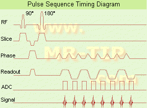
(EPI) Echo planar imaging is one of the early magnetic resonance imaging sequences (also known as Intascan), used in applications like diffusion, perfusion, and functional magnetic resonance imaging. Other sequences acquire one k-space line at each phase encoding step. When the echo planar imaging acquisition strategy is used, the complete image is formed from a single data sample (all k-space lines are measured in one repetition time) of a gradient echo or spin echo sequence (see single shot technique) with an acquisition time of about 20 to 100 ms.
The pulse sequence timing diagram illustrates an echo planar imaging sequence from spin echo type with eight echo train pulses. (See also Pulse Sequence Timing Diagram, for a description of the components.)
In case of a gradient echo based EPI sequence the initial part is very similar to a standard gradient echo sequence. By periodically fast reversing the readout or frequency encoding gradient, a train of echoes is generated.
EPI requires higher performance from the MRI scanner like much larger gradient amplitudes. The scan time is dependent on the spatial resolution required, the strength of the applied gradient fields and the time the machine needs to ramp the gradients.
In EPI, there is water fat shift in the phase encoding direction due to phase accumulations. To minimize water fat shift (WFS) in the phase direction fat suppression and a wide bandwidth (BW) are selected. On a typical EPI sequence, there is virtually no time at all for the flat top of the gradient waveform. The problem is solved by "ramp sampling" through most of the rise and fall time to improve image resolution.
The benefits of the fast imaging time are not without cost. EPI is relatively demanding on the scanner hardware, in particular on gradient strengths, gradient switching times, and receiver bandwidth. In addition, EPI is extremely sensitive to image artifacts and distortions. | | | |
• View the DATABASE results for 'Echo Planar Imaging' (19).
| | |
• View the NEWS results for 'Echo Planar Imaging' (1).
| | | | | | Further Reading: | Basics:
|
|
| |
| | | | | |
| |
|
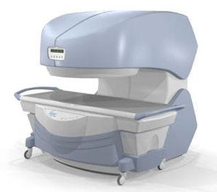
From
Millennium Technology Inc.
This open C-shaped MRI system eases patient comfort and technologist maneuverability. This low cost scanner is build for a wide range of applications. The Virgo™ patient table is detachable and moves on easy rolling castors. Able to accommodate patient weights up to 160 kg, the tabletop has a range of motion of 30 cm in the lateral direction and 90cm in the longitudinal direction. Images generated with this scanner can only be viewed (without data loss) on Millennium's proprietary viewing software.
Device Information and Specification CLINICAL APPLICATION Whole body Head, Body, Neck, Knee, Shoulder,
Spine, Wrist, Breast, Extremity, Lumbar Spine, TMJ
IMAGING MODES Localizer, single slice, multislice, volume, fast, POMP, multi slab, cine, slice and frequency zip, extended dynamic range, tailored RF | | | | | |
| | | Searchterm 'MRI Image' was also found in the following services: | | | | |
| | |
| |
|
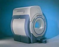
From GE Healthcare;
'EXCITE technology has the potential to open the door to new imaging techniques and clinical applications, leaping beyond conventional two and three-dimensional MRI to true 4D imaging that will improve the diagnosis of disease throughout the human body from head to foot.' Robert R. Edelman, M.D., Professor of Radiology at Northwestern University Medical School and Chairman, Department of Radiology, at Evanston Northwestern Healthcare.
Device Information and Specification CLINICAL APPLICATION Whole body Head and body coil standard; all other coils optional; open architecture makes system compatible with a wide selection of coils Optional 2D/3D brain and prostate Standard: SE, IR, 2D/3D GRE and SPGR, Angiography: 2D/3D TOF, 2D/3D Phase Contrast;; 2D/3D FSE, 2D/3D FGRE and FSPGR, SSFP, FLAIR, EPI, optional: 2D/3D Fiesta, FGRET, Spiral, TensorTR 1.3 to 12000 msec in increments of 1 msec TE 0.4 to 2000 msec in increments of 1 msec 2D 0.7 mm to 20 mm; 3D 0.1 mm to 5 mm 128x512 steps 32 phase encode 0.08 mm; 0.02 mm optional POWER REQUIREMENTS 480 or 380/415 less than 0.03 L/hr liquid heliumSTRENGTH SmartSpeed 23 mT/m, HiSpeed Plus 33 mT/m, EchoSpeed Plus 33 mT/m 4.0 m x 2.8 m axial x radial | | | |
• View the DATABASE results for 'Signa Infinity 1.5T™ with Excite' (2).
| | | | |
| | | | | |
| |
|
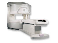
From GE Healthcare;
a friendly and less confining appearance targets the 7% of individuals who refuse to have an MRI because of claustrophobia. This open MRI system is also up to three times faster than other scanners, therefore the Signa OpenSpeed™ reducing exam time and scheduling
issues. In addition, a swing table provides better access and supports up to 500 pounds.
Device Information and Specification CLINICAL APPLICATION Whole body Standard: SE, IR, 2D/3D GRE and SPGR, Angiography: 2D/3D TOF, 2D/3D Phase Contrast;; 2D/3D FSE, 2D/3D FGRE and FSPGR, SSFP, FLAIR, EPI, optional: 2D/3D Fiesta, FGRET, Spiral, TensorTR 1.3 to 12000 msec in increments of 1 msec TE 0.4 to 2000 msec in increments of 1 msec 2D: 0.8mm - 20mm 3D: 0.1mm - 20mm 0.08 mm; 0.02 mm optional POWER REQUIREMENTS 200 - 480, 3-phase | | | |
• View the DATABASE results for 'Signa OpenSpeed™' (2).
| | | | | | Further Reading: | News & More:
|
|
| |
| | | | |
| | |
| | | |
|
| |
 | Look
Ups |
| |


